Friday, December 30, 2011


SYNCHROMESH GEAR BOX

Synchromesh gear box is an automatic means for matching the speeds of engaging dogs. Synchromesh gear box is a device which facilitates the coupling of two shafts rotating at different speeds. Synchromesh unit is used in most of modern gear boxes. In synchromesh gear box, sliding dog clutches are replaced by synchromesh device. The synchromesh devices are used to simplify the operation of changing gear. Synchromesh device helps unskilled drivers to change gears without the occurrence of clashes and damages.

By synchromesh device, the members which ultimately are to be engaged positively are first brought into frictional contact and then when the friction has equalized their speeds, the positive connection is made.


The basic requirements of synchromesh device are:
(1) A braking device such as cone clutch.
(2)  To permit easy meshing means of releasing pressure on the clutch before engagement of gears.

The engine shaft carries a pinion which meshes with a wheel fixed to the layshaft, while the gear on the mainshaft is free to rotate and is permanently meshed with another wheel fixed to the layshaft. Both the pinion and the wheel on the mainshaft have integral dog tooth portions and conical portions. The synchronizing drum is free to slide on splines on the mainshaft. This drum has conical portions to correspond with the conical portions on the gearbox shaft pinion and on the wheel that rotates freely on the mainshaft. The synchronizing drum carries a sliding sleeve. In the neutral position, the sliding sleeve is held in place by the spring loaded balls which rest in the dents in the sliding sleeve (or ring gear). There are usually six of these balls.
In changing gear, the gear lever is brought to the neutral position in the ordinary way, but is immediately pressed in the direction it has to go to engage the required gear. When a shift starts, the spring loaded balls cause the synchronizing drum and sliding sleeve, as an assembly to move toward the selected gear. The first contact is between the synchronizing cones on the selected gear and the drum. This contact brings the two into synchronization. Both rotate at the same speed. When the speeds of the two have become equal, a slightly greater pressure on the gear lever overcomes the resistance of the balls. Further movement of the shift fork forces the sliding sleeve on toward the selected gear. The internal splines on the sliding sleeve i.e. the dog portion, match the external splines on the selected gear the dog teeth are locked up, or engaged, and thus positive connection is established. The gear shift is completed.

CONSTANT MESH GEAR BOX

In constant mesh gear box all the gears are always in mesh and the engagement between the gears which are freely rotating on the transmission main shaft and the transmission main shaft is effected by moving the dog clutches, as explained below.
The engine gear box shaft is integral with a pinion. The pinion meshes with a wheel on the layshaft. The layshaft is therefore driven by the engine shaft. Three more wheels are fixed to the layshaft as in the sliding mesh gearbox. These gears rotate with the layshaft. The transmission main shaft is just above the layshaft and in line with the engine shaft. The three gears (first gear, second gear and reverse gear) on the main shaft are perfectly free to turn on the main shaft. These three gears are in constant mesh with the three wheels on the layshaft. One of these three gears meshes with a wheel on the layshaft through an idler wheel which is mounted and freely rotating on a pin fixed to the gearbox casing. 


The three main shaft gears are, therefore constantly driven by the engine shaft, but at different speeds. The first gear and the second gear rotate in the same direction as the engine shaft while the reverse gear rotates in the opposite direction to the engine shaft.
If anyone of the gears on/the mainshaft is coupled up to the main shaft, then there will be a driving connection between the main shaft and the engine shaft. The coupling is affected by the dog clutch units. The dog clutch members are carried on splined (or squared) portions of the mainshaft. They are free to slide on those squared portions, but have to revolve with the shaft.

If one of the dog clutch members (l) is slid to the left it will couple the wheel (first gear) to the main shaft giving the first gear. The drive is then through the wheels and this dog clutch member. The other dog clutch is meanwhile in its neutral position.
If, with the above dog clutch member in its neutral position, the other dog clutch member (2) is slid to the right, it will couple the wheel (second gear) to the mainshaft and give second gear. If this dog clutch member is slid to the left, it will couple the mainshaft directly to the pinion fixed to the engine shaft. This will give a direct drive, as in the sliding mesh gear box.
The reverse gear is engaged by sliding the dog clutch member (which gives the first gear) to the right. Then it will couple the wheel (reverse gear) to the mainshaft. The drive is then through the wheels, the idler and the dog clutch member.
In the constant mesh gear box, the gears on the mainshaft must be free to revolve. For this, they are either be bushed or be carried on ball or roller or needle bearings.

The main advantages of the constant mesh gear box over the sliding mesh type are as follows:
  1. Helical or double helical gear teeth can be used for the gears instead of spur gears. Then gearing is quieter.
  2. Synchronizing devices can be used for smooth engagement.
  3. Any damage that results from faulty manipulation occurs to the dog clutch teeth and not to the teeth of the gear wheels.
  4. Once the dog clutches are engaged, there is no motion between their teeth. But when gear teeth are engaged, the power is transmitted through the sliding action of the teeth of one wheel on those of the other. The teeth have to be suitably shaped to transmit the motion properly.
  5. If the teeth on the wheel are damaged, the motion will be imperfect and noise will result.
  6.  Damage is less likely to occur to the teeth of the dog clutches, since all the teeth engage at once, whereas in sliding a pair of gears into mesh the engagement is between two or three teeth.

Thursday, December 29, 2011


SLIDING MESH GEARBOX

Sliding mesh gearbox is the oldest and simplest form of gear box. In order to mesh gears on the splined main shaft with appropriate gears on the layshaft for obtaining different speeds, they are moved to the right or left. It derives its name from the fact that the meshing of the gears takes place by sliding of gears on each other.

A three speed sliding mesh gear-box is shown in Figure. Splines are provided on the main shaft. For meshing the pinions with the matching gears on the layshaft, the pinions are slided along the spline. When the main shaft is driven from the layshaft the gear reduction is provided by the first pair of gears which are always in mesh. They are usually known as constant mesh gears. For changing gear the clutch is depressed and the gear lever is moved till the selector pinion on the main shaft engages with its mating gear on the layshaft. The drive from the engine will be again transmitted through the gear-box when the clutch is released. To obtain three forward speeds, reverse and neutral, the relative position of the gears will be as below:

First gear: The largest gear on the main shaft is driven by the smallest gear or pinion on the layshaft. With corresponding increase torque, the speed reduction is quite high. When climbing and moving off steep hill, starting the vehicle from rest this gear is usually used.

Second gear: In this gear, there is less speed reduction and smaller torque increase.

Third or top gear: In order to revolve primary or main shaft at the same speed without any charge in the torque the main shaft is driven through a dog clutch in this gear.

Reverse: In this gear, the peed reduction is usually same as that in the first gear. But the direction of rotation of the main shaft will be reversed by introducing an idler in it. It is due to this change in the direction of rotation of the driving wheels provided by the idler that the motor vehicle moves in reverse direction.

Wednesday, December 14, 2011


TWO-STROKE TRACTOR ENGINES


Two-stroke tractor engines are invariably of the compression-ignition type. Some small cultivators have two-stroke spark-ignition engines also.

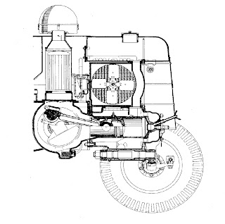
In the two-stroke cycle each downward stroke of the piston is first a power stroke and then an exhaust stroke, and each upward stroke of the piston provides for replenishment of the air charge as well as its subsequent compression. The air for combustion assists removal of the exhaust gases; it is therefore known as 'scavenge' air, and its admission to the engine as 'scavenging’. For efficient scavenging a supply of air is required at a pressure above atmospheric; this can be secured by provision of a 'blower' or by adapting the engine crankcase as an air pump ('crankcase compression scavenging'). A two-stroke engine with a rotary blower of lobed type is shown in Figure 4; in this design exhaust valves are used in the cylinder head, so that the advantages of 'uniflow' scavenging are obtained - i.e. the incoming air sweeps the spent charge out of the cylinder in a generally uniform direction, with relatively little intermixing between the two.

Crankcase-compression scavenging is employed in the exceptionally simple single-cylinder 'valveless' engines of which considerable numbers have been built. An example is shown in Figure 5, and the sequence of events in an engine of this kind is shown in the lower diagram in Figure 6. On the compression stroke of the piston, air is inducted into the crankcase through a non-return valve. On the power stroke the air in the crankcase is compressed to a pressure slightly (perhaps 2 lb./sq.in.) over atmospheric. Near the end of this stroke the piston uncovers an exhaust port in one side of the cylinder wall, and then a 'transfer port' in the other, communicating with the crankcase; the top of the piston (the 'piston crown') is so shaped that the air thus entering the cylinder takes a path promoting scavenging and sweeps residual burnt gases out through the exhaust port. As the piston begins the next stroke it covers both ports and a new cycle follows.

Tuesday, December 13, 2011


FORK LIFTS & LIFT TRUCKS


Fork lifts and lift trucks serve the same purpose in that they transport goods, materials, etc., from one place to another and stack them ready for storage, or load them onto trucks, box cars, etc. On the other hand, a lift truck is designed to operate in rough terrain and has as its power source a conventional wheel tractor. Fork lifts are also self‑propelled machines, but they have smaller wheels which are about 10 to 14 in [25.4 to 35.56cm] in diameter and are of a solid rubber design. The lift capacity and lift height of lift trucks is greater than that of the fork lift. Fork lifts are pow­ered by air‑cooled gasoline or petroleum gas engines or some are battery‑powered, while the larger lift trucks use diesel engines exclusively. However, when the unit has to operate inside buildings they employ petroleum gas engines or battery power to drive the wheel motor and the hydraulic pump. Fork lifts are commonly driven hydrostatically or by electric wheel motors, whereas lift trucks use standard transmissions, power-shift transmissions, or are hydrostatically driven. Four‑speed forward and reverse ranges are used in the standard or power-shift transmissions.
The lift trucks are classified by their lift capacity and lift height. Their lift capacity range is between 1400 and 120,000 lb [65.6 and 54,480 kg]. The lift height range is between 9.6 and 42 ft [2‑9 and 12.81 m]. Depending on the lift capacity, either a conventional drive axle or a drive axle having planetary wheel hubs is used. The fork lift uses band brakes which are hydraulically applied, whereas lift trucks use drum brakes which may be applied hydraulically or by oil or air.

The lift of a fork lift and lift truck is similar in design and in turn, in operating principles. The major components are
• The lift frame
• The mast, consisting of the inner and outer mast
• The single‑acting lift cylinders
• The double‑acting tilt cylinders
• The carriage with the forks


The lift frame is mounted to the tractor, and the outer mast is pivot‑fastened at the bottom to the lift frame. The two double‑acting tilt cylinders are fastened to the lift frame or tractor and the rod ends of the pistons are pivot‑fastened to the outer mast. The inner mast is guided by rollers in the channels of the outer mast. Carriage load rollers and carriage thrust rollers are fastened to the carriage frame to support the carriage and guide it through the inner mast. The lift cylinder is fastened to the lower mast cross member, and the piston rod end is pivot‑fastened to the inner mast cross member (crosshead shaft). The ends of the two lift chains are fastened to the sides of the lift cylinders and placed over guide rollers which are bearing‑supported by the crosshead shaft. The other ends of the lift chains are fastened to the bottom of the carrier frame. The two forks are positioned on the shaft and supported in the bores of the carrier frame, and the lower ends of the forks rest against the lower cross frames.

LIFT OPERATION

Before driving the forks under the pallet or positioning them over the load, the operator must first operate the directional control valve to direct oil to the tilt cylinders, either into the piston ends or into the rod ends of the cylinders, to tilt the mast to a suitable fork position. At the same time the lift cylinder directional control valve must be operated to direct oil into or from the lift cylinders to raise or lower the forks. When raising the load, the piston is forced upward, raising the inner mast. Since the lift chains are fastened to the upper end of the lift cylinder piston, and on the bottom to the carriage frame, the extension of the inner mast raises the carriage frame by this extended distance because the chain is shortened. To lower the load, the directional control valve position is reversed, allowing the oil to flow from the lift cylinder to the directional control valve and back to the reservoir. This removes the force from the piston and the weight, lowering the piston, the inner mast, and the carriage.